What is STA?
Static Timing Analysis (STA) is a technique for estimating the delay of a digital circuit without simulation. Now a days, it is widely adopted in industry for timing verification. This topic will overview the basics of static timing analysis.
How do you ensure after the ASIC is placed and routed, that every register to register path in the design does not violate the setup and hold time? This is where STA tools comes into the picture. Those tools can fully analyze a multimillion gate ASIC in a short amount of time. The STA comes into the picture twice. Once during synthesis and again during place and route. Since Synthesis tools are third party tools, they don't give the precise delays and the delays are based on wire load models which are approximate only. Place and route tools are silicon vendor tools and hence provide better information regarding these delays.
What STA can't do?
STA can only report the paths which are violating a particular constraint. It can't make the TIMINGS MEET. STA tools can't analyze the combinational feedback loops.
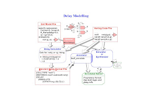
The inputs to any STA tools are going to be verilog netlist, Standard Delay Format (SDF) and Standard Parasitic Extraction Format (SPEF). It also uses the standard cell and macro library to find out the cell delay, net delay & clock to Q output delay of a FF. You also need to have a Design constraint file that will tell the tool about your ASIC. The big picture of Delay modeling is shown in the following Figure.
 Timing Violations:
Timing Constraints:
 Timing Violations:
When your STA tool analyzes your design, it is checking that each path meets the setup and hold time for the design library that you specify. Everyone of us very well know, when will setup time violation occurs. Setup violations occurs when the data path is too slow compared to the clock speed. The designer can fix the setup violations by reducing the delay in the data path. Designer can reduce the clock speed to fix the setup violation, but it is going to be a poor design technique.
Hold violations occurs when data is too fast when compared to the clock speed. If hold violations are not fixed before the chip is made, lot of problem occurs unlike setup violation where the clock speed can be reduced. To fix hold violations, designer can add more delay to the data path.
Hold violations occurs when data is too fast when compared to the clock speed. If hold violations are not fixed before the chip is made, lot of problem occurs unlike setup violation where the clock speed can be reduced. To fix hold violations, designer can add more delay to the data path.
Timing Constraints:
Timing constraints are how the designer tells the STA tool about the timing behavior of the ASIC. The three minimum constraints are defining the clock, input delay, and output delay. There are four types of timing paths are available. They are :
When the clocks are defined, all Register to Register paths are assumed to be constrained in one clock cycle. A path originates from either an Input port or a Register clock pin, while an end point is either an Output port or a Register data pin. All start and end point must be timing constrained.
False paths:
A false path is a path, which exists in the chip but it would never be exercised in the operation of the chip. STA tools can report violations on false paths because there is no knowledge of circuit function.
Multi-Cycle Paths:
A multi-cycle path is when a signal takes more than one clock cycle to propagate to the end point.
Calculation of path delays:
The actual path delay is the sum of net and cell delays. For a given area, average of R and C are calculated for different fanouts. Net delay is calculated by simply multiplying R with C. For example, The R value for a gate that drives 3 gates (Fanout = 3) is say 0.036, the C value for the same gate is for example 0.02, then the net delay is going to be 0.036*0.02.
Two methods for calculating path delays are lumped and pin-pin models. The main difference b/w the two models is how the paths and their delays are defined. Delays are classified either by connection or rise/fall and min/max. For more info. about these delays, readers are advised to refer verilog-HDL by palnitkar.
Report generation from STA tools:
- Input to Register (Sync),
- Register to Register (Sync),
- Register to Output (Sync) and
- Input to Output(Async). Each path has a start and endpoint
When the clocks are defined, all Register to Register paths are assumed to be constrained in one clock cycle. A path originates from either an Input port or a Register clock pin, while an end point is either an Output port or a Register data pin. All start and end point must be timing constrained.
False paths:
A false path is a path, which exists in the chip but it would never be exercised in the operation of the chip. STA tools can report violations on false paths because there is no knowledge of circuit function.
Multi-Cycle Paths:
A multi-cycle path is when a signal takes more than one clock cycle to propagate to the end point.
Calculation of path delays:
The actual path delay is the sum of net and cell delays. For a given area, average of R and C are calculated for different fanouts. Net delay is calculated by simply multiplying R with C. For example, The R value for a gate that drives 3 gates (Fanout = 3) is say 0.036, the C value for the same gate is for example 0.02, then the net delay is going to be 0.036*0.02.
Two methods for calculating path delays are lumped and pin-pin models. The main difference b/w the two models is how the paths and their delays are defined. Delays are classified either by connection or rise/fall and min/max. For more info. about these delays, readers are advised to refer verilog-HDL by palnitkar.
Report generation from STA tools:
Reporting the information stored in STA tool's database allows the user to identify timing violations and make changes to the design. PrimeTime is a famous STA tool that provides extensive commands to report setup, hold, and design rules violations.


6 comments:
You are really doing a wonderful job by putting in some great topics of our field. Keep on doing it!
hi,
thank you sir,
it is very useful for the VLSI student like me,
thank you very much
have a good go
Wow.. it was useful..
Absolutely amazing tutorial...You have explained it in so simple words that anyone can understand the basic funda! Thanks a ton!
its really awesome stuff given here dude... great work....
Thanks a lot. good start to STA...
Post a Comment